Inquiry:

rudy@winack.com
0086-592-7297239
Product description:
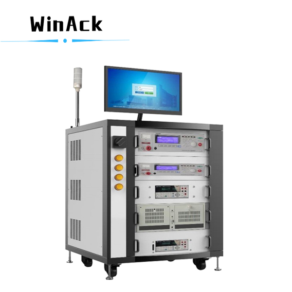
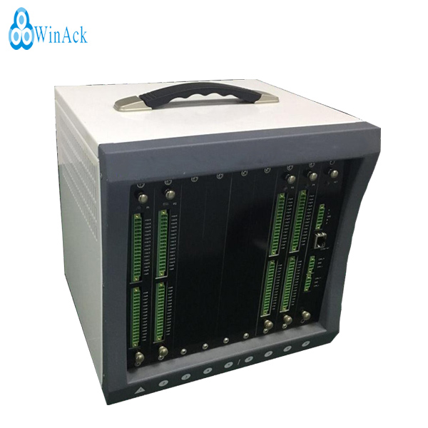
The EV battery pack End-Of-Line test system is specially designed for high-power lithium-ion battery packs. It is mainly used to test and verify the failures and safety issues that may occur during the entire EV battery pack assembly process to ensure that the EV batteries are safe and reliable.
Scope of application:
1.Insulation voltage tester: mainly used for battery insulation function, and AC / DC withstand voltage function.
2. Digital multimeter: test all test items of customer battery voltage.
3. Equipotential tester: test battery leakage.
4. AC internal resistance meter: test the AC internal resistance of customer battery pack.
PS: collect single battery voltage of customer module (module without BMS).
Features:
1. Collection and monitoring of operating parameters.
2. Rate charge and discharge performance test.
3. Insulation withstand voltage safety performance test.
4. The test efficiency is high and it meets the requirements of End-Of-Line test of EV battery pack.
5. Good man-machine interface and easy operation.
6. The verification of the failure mechanism and the test of the response high and low voltage electrical connections.
7. Data can be exchanged with BMU via CAN.
8. It adapts to a variety of battery pack test schemes and is versatile.
9. The test system has excellent heat dissipation performance.
Test Items of the EV Battery
Pack EOL Tester
|
NO. |
Test Item |
Description |
|
1 |
Measuring of total voltage in Pack system |
Read the cell voltage measured by BMS and then calculate the pack voltage V1. Read the pack voltage V2 measured by BMS. The comparison between the V1 and V2 can be used to estimate whether the voltage and measuring accuracy are within the normal range. |
|
2 |
Programming |
Programming and comparison of the battery pack. |
|
3 |
CAN communication test |
Read battery pack initialization information via CAN communication CAN, software. |
|
4 |
Terminal IR test |
Check whether there is insulation resistance (IR) 120/60 Ω in every branch CAN other than paralleling of units via the ohm band of voltmeter. |
|
5 |
Comparison of ambient temperature |
The temperature measured by BMS should be compared with the ambient temperature or it can be compared with other functional ambient temperature for ease of reference. |
|
6 |
BMS insulation alarming test |
Pack positive / negative applies a resistance of ≤ 500 Ω / V to the shell, BMS insulation alarm; Pack positive / negative applies a resistance of ≤100 Ω / V to the shell, BMS insulation alarm. |
|
7 |
PWM signal |
signals with different waves can be used to perform functions, such as charging termination, fast charge activating, ventilator controlling , and ignition signal. |
|
8 |
BMS power supplying test |
Test the BMS malfunction alarming with the voltage of 9-12V on request from client, such as voltage of 12V BMS power supply. |
|
9 |
Power consumption test |
Test the static power consumption of BMS. |
|
10 |
ACIR test |
Test the AC internal resistance (ACIR)of battery pack. |
|
11 |
Earth continuity test |
Test the conducting state of Pack earth circuit. |
|
12 |
Equipotential test |
Test the resistance of Pack equipotential point. |
|
13 |
Pre-charge loop test |
Close the pre-charge loop and read the pre-charging state via CAN. |
|
14 |
High-voltage interlock test |
Test the BMS state and conduction of interlock when the relevant components in the battery pack is connected. Test whether the BMS state is NG when a certain interlock is unconnected. |
|
15 |
Charge communication |
Use CAN card to connect and charge CAN, sending message. If the message can be received, the communication test is considered to be qualified. |
|
16 |
Vehicle communication |
Use CAN card to connect and charge CAN, sending message, if the message can be received, the communication test is considered to be qualified. |
|
17 |
Insulation impedance test |
Respectively test the insulation impedance value of pack positive pole and the pack negative pole against the shell (the ground). |
|
18 |
Withstand voltage test (Positive) |
Turn off the insulation monitoring function. Turn off the insulation monitoring function to test the leakage current: 1) Connect the positive pole of the withstand voltage tester to the positive pole of the battery Pack, the negative pole of the withstand voltage tester to the shell of the battery pack. Then measure the leakage current I1. 2) Connect the positive pole of the withstand voltage tester to the negative pole of the battery Pack, the negative pole of the withstand voltage tester to the shell of the battery pack. Then measure the leakage current I2. |
|
19 |
Withstand voltage test (negative) |
Turn off the insulation monitoring function to test the leakage current: 1) Connect the negative pole of the withstand voltage tester to the positive pole of the battery Pack, the positive pole of the withstand voltage tester to the shell of the battery pack. Then measure the leakage current I1. 2) Connect the negative pole of the withstand voltage tester to the negative pole of the battery Pack, the positive pole of the withstand voltage tester to the shell of the battery pack. Then measure the leakage current I2. |
|
20 |
Fast charge state test |
According to international standard GT27930 protocols, determine whether the fast charge function is normal by automatic connecting of 1000 Ω and enable signal CC2. |
|
21 |
Trickle charge state test |
Trickle charge signal simulation, device output CC, CP signal, and test whether the BMS can read the charging information. |
|
22 |
Heating circuit test |
Close the heating relay, measure the resistance via ohmmeter at the port and judge whether the resistance is within the specified range. |
|
23 |
Relay function test |
Detect whether the battery PACK internal fast charge, trickle charge, heating, main positive, main negative relay condition and combinational control circuit is normal. 1) The upper computer actuates the fast charge, trickle charge, heat, main positive and main negative relay via BMS. 2) Call the multimeter to measure the voltage of fast charge interface, trickle charge interface, discharge interface 3) Read the corresponding relay status value via CAN. |
|
24 |
Charge/discharge loop test |
1.Close the charge/discharge relay by communicating with BMS and measure the total voltage of charge/discharge interface. 2.Disconnect the charge/discharge relay by communicating with BMS and the measured voltage of charge/discharge interface is 0V. |
|
25 |
Single cell voltage difference detection |
The maximum and minimum values of the battery pack string voltage are detected by the BMS. Calculate the difference between the maximum and minimum values. |
|
26 |
Single cell temperature difference detection |
The maximum and minimum temperature values of the battery pack are detected by the BMS. Calculate the difference between the maximum and minimum values. |
|
27 |
Equilibrium diagnosis test |
Send equilibrium directives and detect the equilibrium state. |
|
28 |
HPPC test |
Hybrid Pulse Power test. |
|
29 |
DCR test |
Measure the DC impedance and voltage difference value of the battery pack. Verify the power performance and connecting state. |
|
30 |
Current test |
Current accuracy and current direction test: 1. Check whether the zero current of BMU is correct when the cycling equipment doesn't work. 2.Check whether the current of BMU is in accordance with that of the cycling equipment, when the cycling equipment works normally. 3.Check whether the current direction is correct when checking the test data in charging/discharging. Record the results OK or NG. |
|
31 |
SOC |
Apply the Cycling test system to charge the Pack and read the BMS-SOC value in real time to determine whether the Pack system SOC value meets the specified SOC range value. |
|
32 |
Shipping status detection |
1) Read cell maximum voltage, minimum voltage, cell voltage difference 2) Close the output relay and read the total voltage of the battery pack 3) Read BMS error level, battery health status, and shipping SOC value. |

Contact: Rudy Yan
Phone: 0086- 188 0506 7911
Tel: 0086-592-7297239
Email: rudy@winack.com
Add: WinAck Group, Xiangbei Industrial Zone, Xiamen City, China
 Rudy Yan
 /
/